 English
 русский
 Español
 简体中文
简体中文
Recommended products


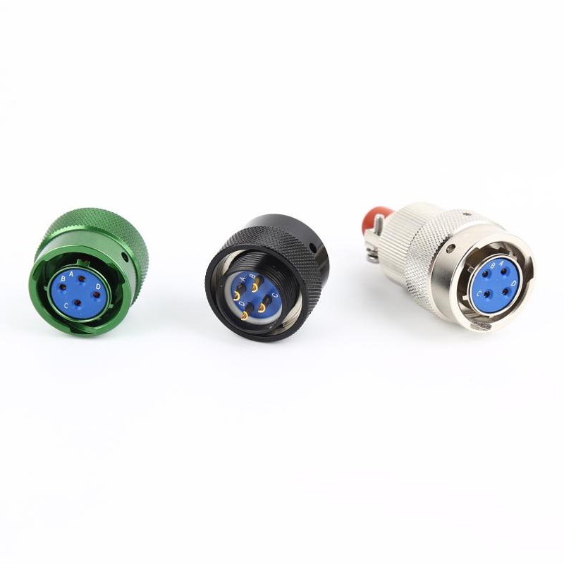
MS26482 Series I Military Electrical Connectors: A Comprehensive Guide
Industry NewsAuthor: Admin
- 1 Understanding MS26482 Series I Connector Specifications
- 2 How to Identify and Select the Right MS26482 Connector
- 3 Common Applications for Military Spec MS26482 Connectors
- 4 Proper Maintenance and Inspection Procedures
- 5 FAQ
- 5.1 What is the difference between MS26482 Series I and Series II connectors?
- 5.2 Are MS26482 connectors compatible with other military connector series?
- 5.3 How do I interpret an MS26482 part number?
- 5.4 What is the typical lifespan and mating cycle rating for these connectors?
- 5.5 Can I use commercial crimp tools for MS26482 contacts?
The MS26482 Series I Military Electrical Connectors represent a cornerstone of reliability in harsh and demanding electrical interconnection environments. Adhering to stringent military specifications, these connectors are engineered for exceptional performance under extreme conditions, including high vibration, wide temperature ranges, and exposure to moisture and contaminants. This guide delves deep into the specifications, applications, and critical selection criteria for these robust components, providing the technical depth needed by engineers, procurement specialists, and maintenance personnel. Understanding the nuances of the MS26482 Series I is paramount for ensuring system integrity in mission-critical applications.
Understanding MS26482 Series I Connector Specifications
The performance and interoperability of MS26482 Series I Military Electrical Connectors are defined by a detailed set of specifications outlined in the governing military standard. These specs cover every aspect from materials and construction to electrical and environmental performance. A thorough grasp of these parameters is essential for proper component selection and system design.
- Shell Size and Style: The MS26482 standard defines specific shell sizes (e.g., 10, 12, 16, 20, 24) which correspond to the physical dimensions and the number of contacts the shell can accommodate. Each shell size has a specific thread for the coupling nut.
- Contact Arrangements: Contacts are available in various sizes (e.g., 16, 20, 22) to handle different current loads. The arrangement (pin or socket) and quantity are specified in the part number.
- Environmental Sealing: These connectors are designed to meet IP67 ratings or better, ensuring protection against dust ingress and water immersion up to specified depths and durations.
- Temperature Range: Typically rated for operation from -65°C to +200°C, depending on the specific materials used for inserts, seals, and backshells.
- Voltage and Current Rating: Ratings are dependent on contact size and the dielectric properties of the insert material, often ranging from 600V to 1000V and currents from 5A to 40A per contact.
Key Material and Construction Features
The durability of these connectors is a direct result of their material composition and robust construction techniques. The choice of materials ensures longevity and reliability in the most challenging environments.
- Shell Material: Typically constructed from cadmium-plated carbon steel or corrosion-resistant stainless steel, providing excellent strength and resistance to environmental degradation.
- Contacts: Made from copper alloy and plated with gold over nickel for superior conductivity, low contact resistance, and exceptional corrosion resistance.
- Insert Material: Molded from thermoset materials like glass-filled epoxy or PTFE, which maintain their structural and dielectric properties across the entire operating temperature range.
- Seals and Grommets: Fabricated from silicone rubber or fluorosilicone compounds, offering excellent compression set and resilience against fluids, ozone, and fungus.
How to Identify and Select the Right MS26482 Connector
Selecting the correct MS26482 Series I Military Electrical Connector involves more than just matching a part number. It requires a systematic approach to ensure the connector meets all electrical, environmental, and mechanical requirements of the application. Misidentification can lead to system failure, making this a critical step.
- Deciphering the Part Number: The complete part number provides a wealth of information, including shell size, connector style (plug or receptacle), contact arrangement, and shell material.
- Assessing Environmental Needs: Evaluate the operational environment. Will the connector be exposed to salt spray, hydraulic fluid, extreme shock, or vibration? The answers will guide material and sealing choices.
- Electrical Requirements: Calculate the total current draw, voltage, and the number of circuits needed. Ensure the chosen contact size and insert material can handle the electrical load with a appropriate safety margin.
- Mating and Unmating Cycles: Consider the required lifespan in terms of connection and disconnection cycles. Commercial versions may have lower cycle life ratings than those meeting the full military standard.
MS26482 vs. Commercial Equivalents: A Critical Comparison
While commercial off-the-shelf (COTS) components may appear similar, the differences between a true military spec MS26482 connector and its commercial equivalent are significant and impact performance, reliability, and longevity. Understanding these distinctions is crucial for making an informed decision.
| Parameter | MS26482 Military Spec | Commercial Equivalent |
| Specification Compliance | Manufactured and tested to strict MIL-DTL-26482 standards | May follow general design but not tested to mil-spec |
| Material Traceability | Full raw material traceability and lot control required | Typically no material traceability |
| Testing and Qualification | Rigorous qualification testing (environmental, mechanical, electrical) | Basic functional testing; no mandatory qualification |
| Performance Guarantee | Guaranteed performance across full specified temperature and environmental range | Performance may not be guaranteed at extremes |
| Cost | Higher due to testing, materials, and documentation | Lower, due to reduced overhead and material costs |
Common Applications for Military Spec MS26482 Connectors
The primary application for MS26482 Series I Military Electrical Connectors is, unsurprisingly, within defense and aerospace systems. However, their proven reliability has led to adoption in any industry where failure is not an option. These connectors are found wherever robust performance is non-negotiable.
- Aerospace and Avionics: Critical wiring systems in aircraft, including flight controls, engine controls, and navigation systems, where vibration and temperature extremes are constant challenges.
- Ground Vehicles and Armor: Used in communications, weapon systems, and power distribution within military tanks, personnel carriers, and support vehicles subjected to shock and EMI.
- Marine and Naval Systems: Ideal for shipboard applications due to their excellent corrosion resistance and ability to seal against saltwater and humidity.
- Industrial Machinery: Employed in heavy industry, mining, and oil & gas applications where equipment faces high levels of dust, moisture, vibration, and chemical exposure.
- Rail Transportation: Suitable for train control systems and passenger information systems that require reliable connectivity in demanding environments.
Proper Maintenance and Inspection Procedures
To ensure the long-term reliability of MS26482 Series I Military Electrical Connectors, a disciplined approach to maintenance and inspection is required. Proper care prevents failures, maintains signal integrity, and extends the service life of both the connector and the entire system.
- Visual Inspection: Regularly inspect for physical damage such as dented shells, cracked inserts, bent or corroded pins, and compromised seals. Check for any signs of arcing or overheating.
- Contact Cleaning: Use approved cleaning solvents and tools, such as lint-free swabs and aerosol cleaners, to remove contamination from pin and socket contacts without causing damage.
- Seal Replacement: Inspect O-rings and other seals for cuts, nicks, or flattening. Replace seals during reassembly and always apply the correct silicone-based lubricant to ensure proper sealing and easier mating.
- Torque Checks: Use a torque wrench to ensure the coupling nut is tightened to the specification outlined in the relevant standard. Overtightening can damage threads, while undertightening can compromise the environmental seal.
- Connector Storage: When not in use, protect connectors with approved dust caps and covers to prevent damage and contamination to the contacts and seals.
Troubleshooting Common Connector Issues
Even with proper maintenance, issues can arise. A systematic troubleshooting approach helps quickly identify and rectify common problems associated with military electrical connectors.
- Intermittent Connection: Often caused by corroded or contaminated contacts, a damaged spring socket, or a loose backshell retaining screw leading to a broken wire.
- High Insertion Loss or VSWR: In RF applications, this can be caused by damaged center contacts, dielectric breakdown, or moisture ingress within the connector.
- Difficulty in Mating: Can result from misaligned connectors, damaged threads, foreign object debris (FOD) inside the shell, or a damaged guide key/keyway.
- Failure to Seal: Usually traced to a missing, damaged, or dry O-ring, a scratched or gouged sealing surface, or an improperly torqued coupling nut.
FAQ
What is the difference between MS26482 Series I and Series II connectors?
The primary difference lies in their size, weight, and performance. The MS26482 Series II Military Connectors were developed as a lighter-weight, higher-density alternative to the Series I. Series II connectors feature a push-pull coupling mechanism instead of a threaded coupling nut, allowing for faster engagement and disengagement. They also offer improved shock and vibration resistance due to their design. While both series are robust, the choice between them often comes down to a trade-off between the proven, rugged threaded design of Series I and the modern, lightweight quick-connect advantages of Series II.
Are MS26482 connectors compatible with other military connector series?
Generally, MS26482 Series I connectors are not directly intermateable with connectors from other common military series, such as MIL-DTL-38999 or MIL-DTL-5015. Each series has unique shell designs, coupling mechanisms, and contact arrangements to prevent accidental mating in complex systems, which is a critical safety feature. However, within the MS26482 series, components from different manufacturers that meet the same detailed specification should be fully intermateable and interchangeable. Always consult the specific technical data sheets to confirm compatibility before interconnection.
How do I interpret an MS26482 part number?
An MS26482 part number is a coded string that reveals the connector's key characteristics. A typical number might look like MS26482-20B10S. Here's a breakdown: "MS26482" is the base specification. The following digits (e.g., "20") indicate the shell size. The letter (e.g., "B") often denotes the connector style (plug, receptacle, jam nut, etc.). The next digits (e.g., "10") specify the contact cavity size and arrangement. The final letter(s) (e.g., "S") can indicate the shell material (e.g., 'S' for stainless steel, 'C' for cadmium-plated steel). For a definitive interpretation, one must always refer to the official governing specification document, MIL-DTL-26482.
What is the typical lifespan and mating cycle rating for these connectors?
The lifespan of a properly maintained MS26482 connector can be decades, as they are designed for long-term reliability in durable equipment. Their mating cycle rating—the number of times they can be connected and disconnected while still meeting all specifications—is typically 500 to 1000 cycles. This high cycle life is achieved through robust materials like hardened steel threads and gold-plated contacts that resist wear. It's important to note that exceeding mechanical limits (e.g., over-torquing), exposing them to unintended chemicals, or failing to keep them clean can significantly reduce their operational lifespan.
Can I use commercial crimp tools for MS26482 contacts?
It is strongly discouraged. While a commercial tool might physically crimp the contact, military spec MS26482 connectors require contacts to be crimped with tools that are specifically calibrated and certified to meet the precise standards outlined in MIL-DTL-26482 and associated contact specifications. Using an uncertified tool can result in an improper crimp—either too tight, which can cut the wire strands and increase resistance, or too loose, which creates a high-resistance connection prone to overheating and failure. Always use the tooling specified in the manufacturer's instructions or the applicable military standard to ensure a reliable, gas-tight connection.


- Address : Jiangping South Road, Zhangqiao Industrial Park, Taixing City, Jiangsu Province, China
- Phone : +86 176 0151 5794
- Whatsapp : +86 176 0151 5794
- Email :[email protected]
- Email :[email protected]
Copyright © Taizhou Henglian Electric Co., Ltd
